

Valve manufacturers publish torques for their products so that actuation and mounting hardware can be properly selected. However, published torque values often represent only the seating or unseating torque for a valve at its rated pressure. While these are important values for reference, published valve torques do not account for actual installation and operating characteristics. In order to determine the actual operating torque for valves, it is necessary to understand the parameters of the piping systems into which they are installed. Factors such as installation orientation, direction of flow and fluid velocity of the media all impact the actual operating torque of valves.
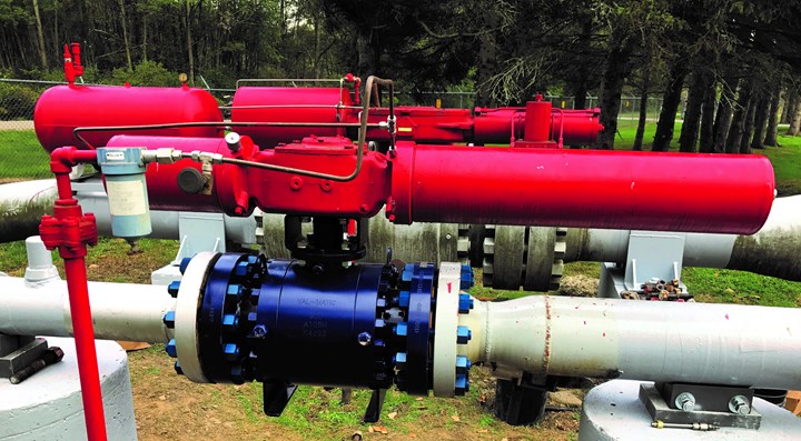
Trunnion mounted ball valve operated by a single acting spring return actuator. Photo credit: Val-Matic
The American Water Works Association (AWWA) publishes detailed information on calculating operating torques for quarter-turn valves. This information appears in AWWA Manual M49 Quarter-Turn Valves: Head Loss, Torque, and Cavitation Analysis. Originally published in 2001 with torque calculations for butterfly valves, AWWA M49 is currently in its third edition. In addition to information on butterfly valves, the current edition also includes operating torque calculations for other quarter-turn valves including plug valves and ball valves. Overall, this manual identifies 10 components of torque that can contribute to a quarter-turn valve’s operating torque.
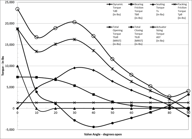
Example torque calculation summary graph
AWWA QUARTER-TURN VALVE HISTORY
The first AWWA quarter-turn valve standard for 3-in. through 72-in. butterfly valves, C504, was published in 1958 with 25, 50 and 125 psi pressure classes. In 1966 the 50 and 125 psi pressure classes were increased to 75 and 150 psi. The 250 psi pressure class was added in 2000. The 78-in. and larger butterfly valve standard, C516, was first published in 2010 with 25, 50, 75 and 150 psi pressure classes with the 250 psi class added in 2014. The high-performance butterfly valve standard was published in 2018 and includes 275 and 500 psi pressure classes as well as pushing the fluid flow velocities above class B (16 feet per second) to class C (24 feet per second) and class D (35 feet per second).
The first AWWA quarter-turn ball valve standard, C507, for 6-in. through 48-in. ball valves in 150, 250 and 300 psi pressure classes was published in 1973. In 2011, size range was increased to 6-in. through 60-in. These valves have always been designed for 35 ft per second (fps) maximum fluid velocity. The velocity designation of “D” was added in 2018.
Although the Manufacturers Standardization Society (MSS) first issued a product standard for resilient-seated cast-iron eccentric plug valves in 1991, the first a AWWA quarter-turn valve standard, C517, was not published until 2005. The 2005 size range was 3 in. through 72 in. with a 175
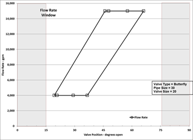
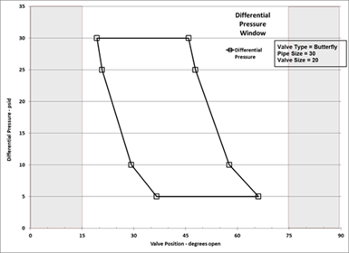
Example butterfly valve differential pressure (top) and flow rate control windows (bottom)
pressure class for 3-in. through 12-in. sizes and 150 psi for the 14-in. through 72-in. The later editions (2009 and 2016) have not increased the valve sizes or pressure classes. The addition of the A velocity designation (8 fps) was added in the 2017 edition. This valve is primarily used in wastewater service where pressures and fluid velocities are maintained at lower values.
The need for a rotary cone valve was recognized in 2018 and the AWWA Rotary Cone Valves, 6 Inch Through 60 Inch (150 mm through 1,500 mm), C522, is under development. This standard will encompass the same 150, 250 and 300 psi pressure classes and the same fluid velocity designation of “D” (maximum 35 feet per second) as the current C507 ball valve standard.
In general, all the valve sizes, flow rates and pressures have increased since the AWWA standard’s inception.
COMPONENTS OF OPERATING TORQUE
AWWA Manual M49 identifies 10 components that affect operating torque for quarter-turn valves. These components fall into two general categories: (1) passive or friction-based components, and (2) active or dynamically generated components. Because valve manufacturers cannot know the actual piping system parameters when publishing torque values, published torques are generally limited to the five components of passive or friction-based components. These include:
Passive torque components:
- Seating friction torque
- Packing friction torque
- Hub seal friction torque
- Bearing friction torque
- Thrust bearing friction torque
The other five components are impacted by system parameters such as valve orientation, media and flow velocity. The components that make up active torque include:
Active torque components:
- Disc weight and center of gravity torque
- Disc buoyancy torque
- Eccentricity torque
- Fluid dynamic torque
- Hydrostatic unbalance torque
When considering all these various active torque components, it is possible for the actual operating torque to exceed the valve manufacturer’s published torque values.
WHY IS M49 MORE IMPORTANT TODAY?
Although quarter-turn valves have been used in the waterworks industry for a century, they are being exposed to higher service pressure and flow rate service conditions. Since the quarter-turn valve’s closure member is always located in the flowing fluid, these greater service conditions directly impact the valve. Operation of these valves require an actuator to rotate and/or hold the closure member within the valve’s body as it reacts to all the fluid pressures and fluid flow dynamic conditions.
In addition to the increased service conditions, the valve sizes are also increasing. The dynamic conditions of the flowing fluid have greater effect on the larger valve sizes. Therefore, the fluid dynamic effects become more important than static differential pressure and friction loads. Valves can be leak and hydrostatically shell tested during fabrication. However, the full fluid flow conditions cannot be replicated before site installation.
Because of the trend for increased valve sizes and increased operating conditions, it is increasingly important for the system designer, operator and owner of quarter-turn valves to better understand the impact of system and fluid dynamics have on valve selection, construction and use.
The AWWA Manual of Standard Practice M 49 is dedicated to the understanding of quarter-turn valves including operating torque requirements, differential pressure, flow conditions, throttling, cavitation and system installation differences that directly influence the operation and successful use of quarter-turn valves in waterworks systems.
AWWA MANUAL OF STANDARD PRACTICE M49 4TH EDITION DEVELOPMENTS
The fourth edition of M49 is being developed to include the changes in the quarter-turn valve product standards and installed system interactions. A new chapter will be devoted to methods of control valve sizing for fluid flow, pressure control and throttling in waterworks service. This methodology includes explanations on the use of pressure, flow rate and cavitation graphical windows to provide the user a thorough picture of valve performance over a range of anticipated system operating conditions.
Read: New Technologies Solve Severe Cavitation Problems
About the Authors
Steve Dalton began his career as a consulting engineer in the waterworks industry in Chicago. He joined Val-Matic in 2011 and was appointed president of Val-Matic in May 2021, following the retirement of John Ballun. Dalton previously worked at Val-Matic as Director of Engineering. He has participated in standards developing organizations, including AWWA, MSS, ASSE and API. Dalton holds BS and MS degrees in Civil and Environmental Engineering along with Professional Engineering Registration.
John Holstrom has been involved in quarter-turn valve and actuator engineering and design for 50 years and has been an active member of both the American Society of Mechanical Engineers (ASME) and the American Water Works Association (AWWA) for more than 50 years. He is the chairperson of the AWWA sub-committee on the Manual of Standard Practice, M49, “Quarter-Turn Valves: Head Loss, Torque and Cavitation Analysis.” He has also worked with the Electric Power Research Institute (EPRI) in the development of their quarter-turn valve performance prediction methods for the nuclear power industry.