
Finite Element Analysis provides data to predict how a seal product will function under certain conditions and can help identify areas where the design can be improved without having to test multiple prototypes.
Here we explain how our engineers use FEA to design optimal sealing solutions for our customer applications.
Why do we use Finite Element Analysis (FEA)?
Our engineers encounter many critical sealing applications with complicating influences. Envelope size, housing limitations, shaft speeds, pressure/temperature ratings and chemical media are all application parameters that we must consider when designing a seal.
In isolation, the impact of these application parameters is reasonably straightforward to predict when designing a sealing solution. However, when you compound a number of these factors (whilst often pushing some of them to their upper limit when sealing) it is crucial to predict what will happen in real application conditions. Using FEA as a tool, our engineers can confidently design and then manufacture robust, reliable, and cost-effective engineered sealing solutions for our customers.
Finite Element Analysis (FEA) allows us to understand and quantify the effects of real-world conditions on a seal part or assembly. It can be used to identify potential causes where sub-optimal sealing performance has been observed and can also be used to guide the design of surrounding parts; especially for products such as diaphragms and boots where contact with adjacent parts may need to be avoided.
The software also allows force data to be extracted so that compressive forces for static seals, and friction forces for dynamic seals can be accurately predicted to help customers in the final design of their products.
How do we use FEA?
Starting with a 2D or 3D model of the initial design concept, we apply the boundary conditions and constraints supplied by a customer; these can include pressure, force, temperatures, and any applied displacements. A suitable finite element mesh is overlaid onto the seal design. This ensures that the areas of most interest return accurate results. We can use larger mesh sizes in areas with less relevance (or lower levels of displacement) to minimise the computing time required to solve the model.
Material properties are then assigned to the seal and hardware components. Most sealing materials are non-linear; the amount they deflect under an increase in force varies depending on how large that force is. This is unlike the straight-line relationship for most metals and rigid plastics. This complicates the material model and extends the processing time, but we use in-house tensile test facilities to accurately produce the stress-strain material models for our compounds to ensure the analysis is as representative of real-world performance as possible.
What happens with the FEA data?
The analysis itself can take minutes or hours, depending on the complexity of the part and the range of operating conditions being modelled. Behind the scenes in the software, many hundreds of thousands of differential equations are being solved.
The results are analysed by our experienced seal designers to identify areas where the design can be optimised to match the specific requirements of the application. Examples of these requirements could include sealing at very low temperatures, a need to minimise friction levels with a dynamic seal or the seal may need to withstand high pressures without extruding; whatever sealing system properties are most important to the customer and the application.
Results for the finalised proposal can be presented to the customer as force/temperature/stress/time dashboards, numerical data and animations showing how a seal performs throughout the analysis. This information can be used as validation data in the customer’s system design process.
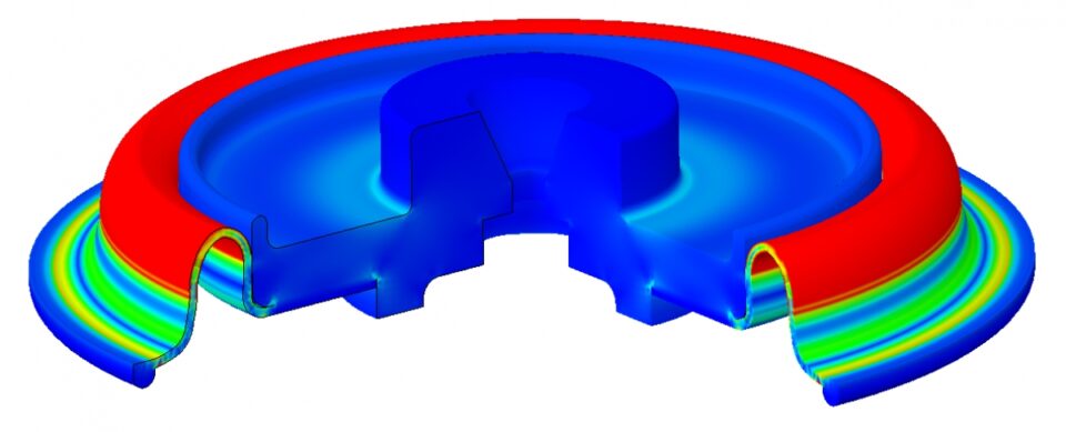
An example of FEA
Faced with very tight packaging constraints, this customer requested a diaphragm component for a valve application. By using FEA, we were able to optimise the design; not only of the elastomer diaphragm itself, but also to propose modifications to the hardware components that interfaced with it to increase the available space for the diaphragm. This kept material stress levels low to remove any possibility of fatigue failure of the diaphragm over the life of the valve.